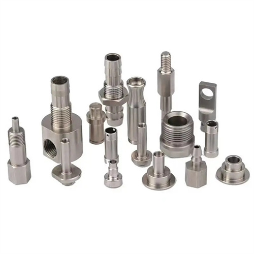
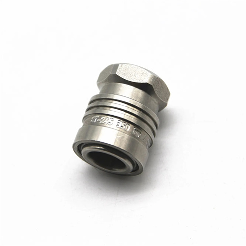
CNC Machining of cast iron spherical joints
Cast iron internal spherical joints are key components for achieving multi-angle rotational motion in mechanical transmissions and are widely used in hydraulic cylinders for construction machinery, robotic joints, and automotive suspension systems. Their structural characteristics are characterized by a precisely spherical inner surface, which mates with an outer spherical component to form a revolute pair. This spherical surface requires high dimensional accuracy (diameter tolerance IT7-IT8), form precision (roundness ≤ 0.01mm), and surface quality (Ra ≤ 1.6μm) to ensure flexibility and tightness. Cast iron materials (such as HT300 and QT500-7) offer excellent wear resistance and vibration damping, but they are also quite brittle. CNC Machining the internal spherical surface can easily lead to edge chipping and surface roughness, necessitating the use of specialized tools and processes to ensure quality.
The selection of turning tools for cast iron internal spherical joints requires a balance between spherical surface forming accuracy and cutting efficiency. Commonly used tools include forming tools, ball-end turning tools, and arc turning tools. Forming tools, with their cutting edge shaped to match a portion of the sphere, are suitable for mass production and can complete spherical CNC machining in a single feed. Tool materials include YG-type carbide (such as YG6 and YG8), with a rake angle of 0°-5° and a relief angle of 6°-8°. The cutting edge must be finely ground to an edge roughness of Ra ≤ 0.025μm to avoid tool marks on the machined surface. Ball-end turning tools are suitable for single-piece, small-batch production. They feature a hemispherical tool head with a radius equal to the radius of the sphere being machined. Spherical CNC machining can be achieved through manual feed or CNC interpolation. High-speed steel (such as W18Cr4V) is suitable for fine turning, while carbide (such as YW1) is suitable for rough turning. The cutting edge of the arc turning tool is an arc segment. The spherical radius is controlled by adjusting the distance between the tool center and the workpiece rotation center. It is suitable for processing large-sized internal spheres (diameter ≥ 200mm). The tool shank needs to be thickened to a diameter of 30-50mm to ensure rigidity and avoid vibration.
Clamping and alignment of cast iron internal spherical joints are crucial for ensuring accurate positioning of the spherical center. The appropriate clamping method must be selected based on the workpiece structure. For internal spherical joints with flanges, a faceplate clamping system is used, with the flange end face and outer diameter used for positioning. Clamping is performed evenly with a pressure plate. Alignment is performed to maintain radial runout of ≤0.02mm and axial runout of ≤0.03mm, ensuring that the spherical center coincides with the workpiece’s rotational center, with a positioning error of ≤0.03mm. For cylindrical internal spherical joints without flanges, a three-jaw chuck and tailstock double-top clamping system are used, with positioning performed using the inner or outer diameter at each end. Alignment maintains radial runout of ≤0.02mm to prevent elliptical or eccentric spherical surfaces during CNC machining. During clamping, copper pads should be placed between the workpiece and the jaws to increase contact area. The clamping force should be controlled between 800-1200N to prevent workpiece deformation. For thin-walled parts (wall thickness ≤5mm), additional supports should be added, located 1/3 of the way between the ends of the spherical surface to reduce CNC machining vibration.
There are three methods for turning cast iron internal spherical joints: manual feed, profiling, and CNC turning. Different methods are suitable for different production batches and precision requirements. The manual feed method is suitable for single-piece, small-batch production. By operating the middle and small slides with both hands, the tool is fed along the spherical trajectory. During CNC machining, the spherical radius must be measured multiple times to gradually approach the required size. This method is suitable for applications with low precision requirements (radius error ≤ 0.1mm). The profiling method is suitable for medium-batch production. A profiling device controls the tool feed trajectory. The profiling arc radius is consistent with the workpiece spherical radius. The contact between the roller and the profiling drives the tool movement, ensuring a spherical radius error of ≤ 0.03mm and a surface roughness of Ra ≤ 3.2μm. The CNC turning method is suitable for large-scale, high-precision internal spherical surface processing. By programming the circular interpolation program, the tool is controlled to move along the spherical generatrix with a uniform feed speed (50-100mm/min). The spherical roundness can be guaranteed to be ≤0.005mm, the radius error ≤0.01mm, and the surface roughness Ra ≤1.6μm. It is currently the most efficient and most stable processing method.
Cutting parameters for cast iron internal spherical joints must be appropriately set according to the CNC machining stage and tool material to balance efficiency and surface quality. For rough turning, carbide tools are used at a cutting speed of 60-80 m/min, a feed rate of 0.2-0.3 mm/r, and a depth of cut of 1-2 mm. Stock removal is rapid, leaving a 0.5-1 mm allowance for the spherical radius. During finish turning, careful chip removal is crucial to prevent chips from accumulating at the bottom of the spherical surface and scratching the surface. For finish turning, high-speed steel or ultra-fine-grain carbide tools are used at a cutting speed of 40-60 m/min, a feed rate of 0.05-0.1 mm/r, and a depth of cut of 0.1-0.3 mm. Kerosene or extreme-pressure emulsion is used as the cutting fluid for adequate cooling and lubrication to minimize tool wear. For ductile iron (QT500-7), due to its higher strength and toughness, the cutting speed should be reduced by 10%-15%, and the feed rate should be appropriately reduced to prevent tool chipping. During the CNC machining process, the spherical radius needs to be measured every 0.5mm feed, and checked with an inside micrometer or spherical template to ensure that the final size meets the requirements.
Quality inspection and error correction for cast iron internal spherical joints require specialized tools and methods to ensure spherical surface accuracy. The spherical radius is inspected using a spherical gauge or a three-dimensional coordinate measuring machine. The gauge should be painted to ensure that the contact area is ≥80%, with contact marks evenly distributed in the center of the sphere. The three-dimensional coordinate measuring machine can accurately measure the coordinates of each point on the sphere and, compared to the theoretical center of the sphere, maintain a radius error of ≤0.01mm. Roundness is inspected using a roundness tester, measuring the roundness of different sections of the sphere with an error of ≤0.01mm. Surface roughness is measured using a roughness tester, with an Ra value of ≤1.6μm. After finish turning, surface burrs should be removed. This can be achieved by lightly polishing along the tangent line of the sphere with fine emery cloth. Common quality issues and solutions: If the spherical radius is out of tolerance, adjust the tool position or guide parameters and retry cutting. If the sphere appears elliptical, check the coaxiality of the workpiece clamping and realign it. If chatter marks are present on the surface, reduce the cutting speed, increase tool rigidity, or adjust the spindle speed to avoid resonant frequencies. For internal spherical joints with extremely high precision requirements (such as hydraulic servo systems), grinding or honing is required after turning to further improve the surface quality (Ra≤0.025μm) and shape accuracy to meet the requirements of high-pressure sealing and low friction.