Cutting parameters for CNC machining slender shafts
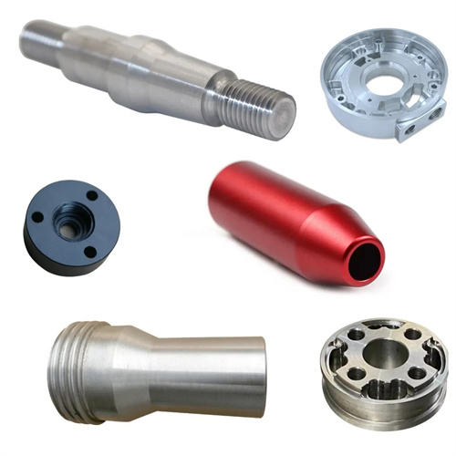
Slender shafts are typical components commonly found in CNC machining, typically referring to shaft parts with a length-to-diameter ratio (A/D ratio) greater than 20, such as machine tool spindles and lead screws. Due to their poor rigidity and weak bending resistance, they are prone to bending, deformation, and vibration during the cutting process. This not only affects the dimensional and shape accuracy of the part, but also degrades surface quality and can even lead to workpiece scrap. The proper selection of cutting parameters is a key factor in controlling the CNC machining quality of slender shafts. These parameters, including cutting speed, feed rate, and depth of cut, interact with each other and require comprehensive optimization based on the slender shaft’s material properties, structural dimensions, CNC machining method, and precision requirements.
The choice of cutting speed is crucial for slender shaft CNC machining, directly affecting cutting temperature, tool wear, and surface quality. For slender steel shafts, if the cutting speed is too low (less than 50 m/min) during rough CNC machining, built-up edge (BUE) can easily occur, resulting in increased surface roughness and high cutting forces, which can easily cause workpiece bending and deformation. If the cutting speed is too high (over 150 m/min), the cutting temperature rises sharply, exacerbating tool wear and even causing workpiece bending due to thermal deformation. Therefore, when rough turning slender steel shafts, the cutting speed should be controlled between 80-120 m/min to avoid BUE while ensuring high CNC machining efficiency. During finish CNC machining, to improve surface quality, the cutting speed can be increased to 120-180 m/min. This reduces workpiece deformation by utilizing the low cutting forces of high-speed cutting. However, high-performance cutting fluids are required to reduce cutting temperatures. For slender non-ferrous metal shafts (such as aluminum alloys), due to their good thermal conductivity and low plasticity, the cutting speed can be increased to 200-300 m/min to achieve even better surface quality.
Feed rate directly affects cutting forces and surface roughness, and is particularly critical for controlling deformation on slender shafts. During roughing, a higher feed rate (0.3-0.5 mm/r) can be used to quickly remove excess material. However, it should be noted that excessive feed rates can increase radial cutting forces, causing workpiece vibration and bending deformation. Therefore, appropriate adjustment is required based on the depth of cut. For example, when the depth of cut is 3-5 mm, a feed rate of 0.3-0.4 mm/r is suitable, ensuring a high removal rate while avoiding excessive cutting forces. During finishing, a lower feed rate (0.1-0.2 mm/r) is required to reduce surface roughness. This reduces cutting forces and workpiece deformation, helping to ensure CNC machining accuracy. However, a feed rate that is too low (less than 0.1 mm/r) increases the compressive force between the tool and the workpiece surface, potentially leading to increased surface hardening and compromising surface quality. Therefore, optimization is necessary based on tool type and workpiece material. For example, when using carbide tools to finish CNC machining a 45 steel slender shaft, the feed rate is 0.12-0.15mm/r, and a surface roughness of Ra1.6-Ra3.2μm can be obtained.
The selection of cutting depth requires a balance between CNC machining efficiency and workpiece rigidity, and is one of the primary factors affecting deformation in slender shafts. During roughing, the majority of the CNC machining stock should be removed in a single pass to minimize tool passes and workpiece deformation caused by multiple clamping. However, excessive cutting depth can lead to a sharp increase in radial cutting forces, causing bending and vibration in slender shafts. Therefore, the cutting depth during roughing is generally controlled between 2-5mm, with the specific value determined based on the workpiece diameter and rigidity. For example, for a slender shaft made of 45 steel with a diameter of 20mm and an aspect ratio of 30, a cutting depth of 3-4mm is appropriate during roughing, ensuring high CNC machining efficiency while avoiding excessive workpiece deformation. During semi-finishing and finishing, the cutting depth should be gradually reduced, from 1-2mm for semi-finishing to 0.5-1mm for finishing, to gradually correct for workpiece shape errors and improve CNC machining accuracy. Furthermore, the cutting depth should be allocated according to the principle of “large first, then small”: a larger cutting depth during roughing to quickly remove the stock, and a gradually reduced cutting depth in subsequent steps to control deformation and ensure accuracy.
Proper matching of cutting parameters is crucial for slender shaft CNC machining. This requires synergistic optimization of cutting speed, feed rate, and depth of cut to achieve a balance between CNC machining quality and efficiency. In actual production, a combination of “high speed, low feed” or “low speed, high feed” strategies can be employed. For workpieces with poor rigidity (aspect ratio greater than 30), a higher cutting speed (120-150 m/min), lower feed rate (0.1-0.15 mm/r), and depth of cut (1-2 mm) are recommended to reduce cutting forces and control deformation. For workpieces with relatively good rigidity (aspect ratio of 20-30), a moderate cutting speed (80-100 m/min), higher feed rate (0.2-0.3 mm/r), and depth of cut (3-4 mm) can be employed to improve CNC machining efficiency. Furthermore, appropriate cutting fluids and clamping methods are essential, such as using extreme pressure emulsions for high-pressure cooling and employing a clamping, top-loading, and heel-rest clamping method to further minimize workpiece deformation. By scientifically matching the cutting amount, the deformation and vibration during the processing of slender shafts can be effectively controlled, ensuring the dimensional accuracy, shape accuracy and surface quality of the parts, and meeting the use requirements of mechanical products.