CNC Machining of three-start worm gear sleeve
A three-start worm gear is a transmission component with an internal thread. Its inner wall is machined with three helical worm teeth. It works with the three-start worm to achieve speed reduction or motion conversion. It is widely used in machine tools, lifting machinery, automation equipment, and other fields. The tooth profile of a three-start worm gear is complex and requires high precision (typically grade 6 or 7). During CNC machining, pitch error, tooth profile error, and surface quality must be guaranteed. CNC Machining, a key process, involves challenges such as tool selection, helical processing, and precision control, necessitating a specialized process solution.
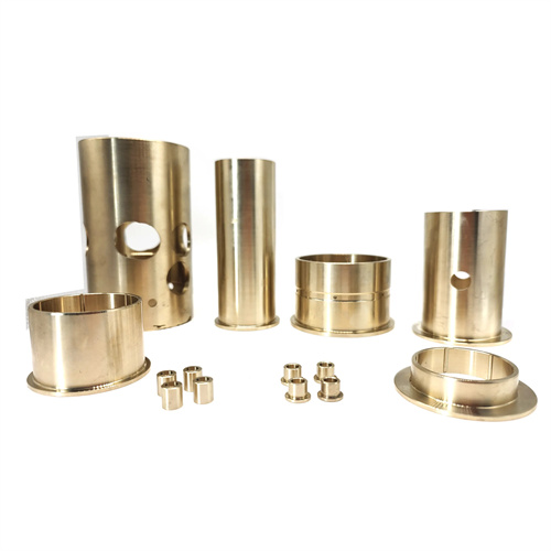
The structural characteristics and CNC machining difficulties of a three-start worm gear sleeve determine the unique nature of its turning process. The inner hole of a three-start worm gear sleeve is usually a through hole or a blind hole. The helical direction of the worm teeth can be left-handed or right-handed. The lead angle is determined by the transmission ratio and is generally 5°-30°. Its CNC machining difficulties are mainly reflected in three aspects: first, the phase control of the three-start helical lines. The three helical lines must be evenly distributed (with a phase angle difference of 120°), otherwise it will lead to poor meshing; second, the assurance of tooth profile accuracy. The tooth profile angle (usually 40°) and tooth thickness of the worm teeth must be precise to ensure smooth transmission; third, the lack of rigidity in internal thread processing, especially for thin-walled worm gear sleeves, is prone to vibration and deformation during turning, affecting CNC machining accuracy. Therefore, before turning, a detailed process route must be formulated, suitable processing equipment (such as a CNC lathe or a dedicated worm processing machine) must be selected, and high-precision indexing devices and cutting tools must be equipped.
Rough turning and semi-finishing the inner bore of a three-start worm sleeve lay the foundation for subsequent worm gear CNC machining, ensuring dimensional accuracy and surface quality. The inner bore diameter is typically IT8-IT9, with a surface roughness Ra of 3.2-6.3μm, serving as the benchmark for worm gear CNC machining. Roundness and cylindricity tolerances must be controlled within 0.01-0.02mm. During rough turning, a twist drill or boring tool is used to machine the inner bore, allowing a 1-2mm allowance for semi-finishing. Semi-finishing uses a carbide boring tool at a cutting speed of 80-120m/min, a feed rate of 0.15-0.25mm/r, and a depth of cut of 0.5-1mm to ensure dimensional accuracy and surface quality. For thin-walled worm sleeves, semi-finishing requires a rigid toolholder to minimize deformation caused by cutting forces. A reverse cutting method (feeding the tool from the hole opening to the bottom) can be used to offset some radial forces with cutting forces. After semi-finishing, the actual size of the inner hole needs to be measured to provide accurate benchmark data for the finish turning of the worm gear.
The rough turning of the three-start worm gear sleeve tooth profile requires solving the problems of spiral line processing and phase angle control. A worm turning tool is used for rough turning, and spiral feed is achieved through the screw drive of the lathe. For CNC lathes, the spiral motion trajectory of the tool can be directly controlled by programming. In order to ensure the uniform distribution of the three spiral lines, after rough turning the first spiral line, the workpiece must be rotated 120° through the indexing device, and then the second and third spiral lines are processed. The indexing accuracy must be controlled within ±5′. The geometric parameters of the worm turning tool must match the worm tooth profile. The front angle of the rough turning tool is 5°-10°, the back angle is 6°-8°, and the tooth profile angle is sharpened according to the nominal angle of the worm (generally 40°). The tool tip arc radius is slightly smaller than the tooth bottom arc radius. Cutting parameters are selected to remove the majority of the stock. A cutting speed of 50-80 m/min (for carbide tools) and a feed rate of 0.1-0.2 mm/min are recommended. The cutting depth should be 2/3 of the tooth height. Tooth thickness should be measured after each feed to avoid overcutting. For worm gears with large lead angles, the effect of the helix angle on the tool’s actual rake and relief angles should be considered. Compensation should be achieved by adjusting the toolholder angle to ensure smooth cutting.
Finish turning the tooth profile of a three-start worm gear is crucial for ensuring transmission accuracy. Strict control of pitch error, tooth profile error, and surface quality is essential. High-precision worm turning tools made of high-speed steel or ultrafine-grain carbide are used for finish turning. The cutting edges are finely ground to a surface roughness Ra of no greater than 0.025μm, and the tooth profile angle error is controlled within ±10°. Cutting parameters should be appropriately reduced: cutting speeds of 30-50m/min, feeds of 0.05-0.1mm/r, and depths of cut of 0.1-0.3mm to reduce cutting forces and vibration. During the finish turning process, tooth thickness and pitch should be measured using a dial indicator or specialized measuring tools. The cumulative pitch error is generally controlled within 0.02-0.05mm/100mm, and the tooth thickness limit deviation meets design requirements (usually h11 or g11). For mass-produced worm gears, specialized templates or gauges can be used for inspection to ensure tooth profile consistency. The surface roughness Ra value of the worm gear teeth after fine turning should reach 1.6-0.8μm. If the surface quality is insufficient, honing or grinding can be performed, but care must be taken to avoid affecting the tooth profile accuracy.
The clamping method and process equipment used in turning three-start worm gear sleeves significantly affect CNC machining accuracy. For small and medium-sized worm gear sleeves, a three-jaw self-centering chuck can be used for clamping, combined with axial positioning to ensure coaxiality. For large or thin-walled worm gear sleeves, soft jaws or special clamps are required to increase the contact area and reduce clamping deformation. During CNC machining, a tool rest or boring bar support is required to increase the rigidity of the tool system and avoid vibration. To ensure the phase accuracy of the three helical lines, a high-precision indexing device is required, such as the C-axis of a CNC lathe (indexing accuracy can reach ±1′) or a mechanical indexing head (indexing accuracy ±5′). In addition, the lathe’s leadscrew pitch error and spindle radial runout must be regularly calibrated. The pitch error can be corrected using the leadscrew compensation function, and the spindle radial runout should be controlled within 0.01mm. After turning, the worm sleeve needs to be inspected as a whole, including the coaxiality between the inner hole and the worm teeth, and the perpendicularity between the end face and the axis. The coaxiality error generally does not exceed 0.02mm, and the perpendicularity error does not exceed 0.01mm/m to ensure the transmission accuracy after assembly. Through reasonable clamping, high-precision process equipment and strict process control, high-quality turning processing of three-start worm sleeves can be achieved to meet the use requirements of the transmission system.
