Processing technology of sleeves and gears
Sleeves and gears are core components in mechanical transmission systems. Sleeves primarily serve as supports, guides, or seals, while gears transmit motion and power. The processing quality of both directly impacts the precision and lifespan of mechanical products. The CNC machining process for sleeves and gears is tailored to material properties, structural complexity, and precision requirements, encompassing multiple steps including blank preparation, heat treatment, and CNC machining. Sleeves prioritize inner bore accuracy and inner and outer circle coaxiality, while gears emphasize tooth profile accuracy, pitch uniformity, and contact precision. The two processes share both similarities and differences.
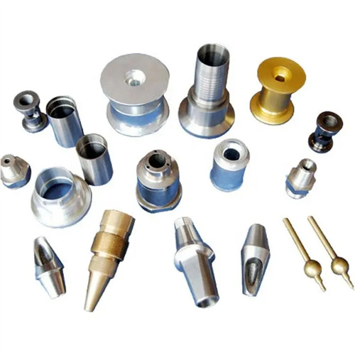
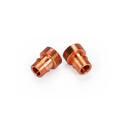
The CNC machining process for sleeve-type parts focuses on ensuring the coaxiality of the inner and outer diameters. The typical process is: forging or casting the blank → annealing (stress relief) → rough turning the outer diameter, end faces, and inner bore → quenching and tempering (to increase hardness) → semi-finishing the outer diameter, end faces, and inner bore (leaving a 0.5-1mm allowance) → drilling radial holes (if necessary) → heat treatment (such as surface hardening) → rough grinding the inner bore → fine grinding the outer diameter → fine grinding the inner bore → inspection. The rough CNC machining stage is performed on a lathe, using the outer diameter or end face of the blank for positioning and rapid stock removal. Semi-finishing uses the inner bore or outer diameter as a reference, employing a mutual reference method to ensure coaxiality (generally ≤ 0.02mm) between the inner and outer diameters. For sleeves with high precision requirements (such as bearing sleeves), fine grinding the inner bore requires a centerless grinder or internal cylindrical grinder to ensure a roundness of ≤ 0.005mm and a surface roughness of Ra 0.4μm. If the sleeve has a keyway or oil hole, it should be machined after semi-finish turning and before heat treatment to prevent heat treatment deformation that affects positioning accuracy. Regarding material selection, 45 steel is used for ordinary sleeves, while 20CrMnTi (carburized and quenched) or GCr15 (quenched and tempered) is used for high-precision sleeves to improve wear resistance and dimensional stability.
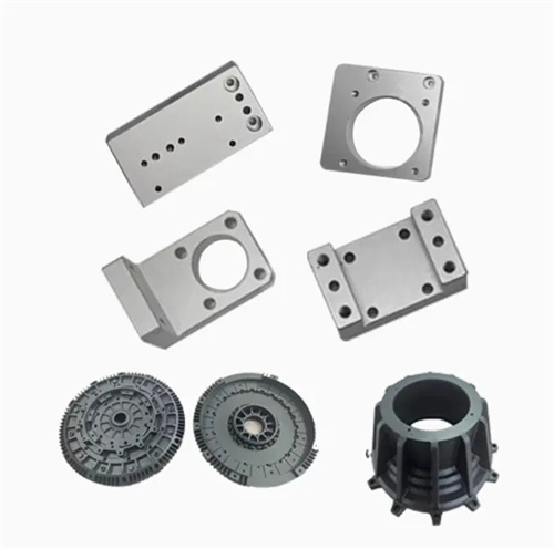
Gear CNC machining requires a balanced approach to both gear blank accuracy and tooth profile quality. The typical process is: forging the blank → normalizing (to improve cutting performance) → rough turning the gear blank (external diameter, end face, and internal bore) → quenching and tempering (220-280 HBW) → finish turning the gear blank (to ensure reference surface accuracy) → gear shaping or hobbing (rough tooth profile) → tooth end rounding → carburizing and quenching (tooth surface hardness 58-62 HRC) → honing or grinding (finishing the tooth profile) → inspection. Gear blank CNC machining is fundamental to ensuring gear accuracy. After finish turning, the internal bore tolerance must be controlled within IT6-IT7, with reference end face flatness ≤0.01mm and external diameter/internal bore coaxiality ≤0.015mm. The tooth profile processing method is selected based on the precision level: gears below grade 7 use hobbing and shaving; gears grade 6-5 use hobbing, carburizing and quenching, and honing; and high-precision gears grade 4 and above require hobbing, quenching, and grinding. Hobbing requires a cumulative pitch error of ≤0.03mm/100mm and a tooth profile error of ≤0.01mm. Grinding can further reduce the tooth profile error to within 0.005mm, meeting the requirements for high-speed, heavy-duty gears. Regarding materials, 45 steel is used for medium- and low-speed gears, while 20CrNiMo or 18Cr2Ni4WA is used for high-speed, heavy-duty gears to improve tooth surface contact strength and tooth root bending strength.
The heat treatment process used in sleeve and gear manufacturing plays a decisive role in component performance. Heat treatment for sleeve components should be selected based on functional requirements: Sleeves used for support require quenching and tempering (220-250 HBW) to ensure sufficient strength and toughness; sleeves used for sliding friction require surface hardening (hardness 50-55 HRC) to improve wear resistance, followed by low-temperature tempering to relieve stress. Gear heat treatment is divided into preliminary heat treatment and final heat treatment. Preliminary heat treatment (normalizing or quenching and tempering) improves CNC machining performance and achieves a uniform metallographic structure; final heat treatment (carburizing or surface hardening) increases tooth surface hardness. The carburized layer depth is determined by the gear module (generally 0.8-1.2 μm, where μm represents the module). Tempering (180-200°C) is necessary after quenching to reduce residual stress. Heat-treated parts should be inspected for deformation. The internal bore shrinkage of sleeves is generally 0.01-0.03 mm, while the tooth profile deformation of gears should be ≤0.01 mm. Parts that exceed tolerances require straightening or secondary CNC machining. For high-precision parts, aging treatment (such as artificial aging at 200℃×4h) is required after heat treatment to further stabilize the dimensions.
Precision inspection methods for sleeve and gear manufacturing must be determined based on quality requirements. Inspection criteria for sleeve parts include: inner bore diameter (using an inside micrometer), outer diameter (using an outside micrometer), inner and outer diameter coaxiality (measured using a dial indicator on a runout gauge), and end face perpendicularity (using a square and feeler gauge). High-precision sleeves also require inspection for inner bore cylindricity (using a cylindricity tester) and surface roughness (using a roughness tester). Gear inspection criteria include: tooth blank reference surface accuracy (for sleeve parts), pitch deviation (using a pitch gauge), tooth profile error (using an involute tester), tooth profile error (using a tooth profile tester), and contact spot (using a coloring method). For mass-produced gears, a double-flank gear meshing tester can be used to rapidly inspect radial combined error, with a throughput of up to 50-100 units per hour. During inspection, attention must be paid to the ambient temperature (20±2°C) to avoid measurement errors caused by temperature fluctuations. Before precision measurement, parts must be placed in a constant temperature environment for 2-4 hours to ensure consistency with the ambient temperature.
Process optimization for sleeve and gear CNC machining can significantly improve production efficiency and quality consistency. For sleeve CNC machining, composite tools (such as a combination tool that simultaneously turns the outer diameter, end face, and inner bore) can be used to reduce tool change time by 30%-50%. For thin-walled sleeves, rigid toolholders and reverse cutting methods can be used to minimize CNC machining distortion (deformation can be controlled to within 0.01mm). High-speed hobbing (cutting speeds of 100-200m/min) and dry cutting techniques can be used for gear CNC machining to improve efficiency and reduce environmental pollution. CNC gear grinding machines can automatically correct tooth profile and tooth profile, reducing scrap rates to below 0.5%. Furthermore, the introduction of digital manufacturing technologies, such as CNC machining code generation through CAD/CAM systems, enables seamless integration from design to CNC machining. Online measurement systems provide real-time feedback on CNC machining errors, allowing machine tool compensation functions to automatically adjust parameters to ensure part consistency. Through process optimization, sleeve and gear production cycles can be shortened by 20%-40%, reducing manufacturing costs by 15%-25%, while meeting higher precision requirements.