CNC Machining of Large Inner Tapered Holes in Cast Iron
Large internal tapered holes in cast iron (taper 1:5 or greater, large-end diameter ≥100mm) are key components in cast iron housings, machine tool spindle boxes, and other cast iron components. They are used to mount bevel gears, centers, or seals. CNC Machining accuracy directly impacts transmission efficiency and positioning accuracy. Cast iron materials (such as HT200 and HT300 ) have moderate hardness (180-250 HBW), are brittle, and easily generate chip breakage during cutting. CNC Machining large internal tapered holes presents challenges such as rapid tool wear, high surface roughness, and difficulty controlling taper accuracy. Specialized tools, optimal clamping, and optimized cutting parameters are required to ensure dimensional accuracy (IT7-IT8), taper error (≤0.01mm/100mm), and surface roughness (Ra ≤3.2μm).
The selection of turning tools for large inner tapered holes in cast iron needs to take into account both wear resistance and chip removal performance. Commonly used tool materials include cemented carbide and high-speed steel. When CNC machining common gray cast iron such as HT200, YG-type cemented carbide (such as YG8 and YG6) is preferred. They offer excellent toughness, strong impact resistance, and are less susceptible to chipping. The tool’s rake angle is 0°-5°, the clearance angle 6°-8°, and the lead angle is determined by the taper angle, equal to half of the taper angle. For example, when CNC machining a tapered hole with a 1:10 taper (5°43′), the lead angle is 2°51′30″. The tool head adopts a positive rake angle, with a wide chip flute (8-12mm wide) ground on the rake face and a flute bottom radius of R3-R5 to facilitate chip evacuation and prevent chip scratches on the machined surface. For finish turning, high-speed steel tools (such as W18Cr4V) can be used. The cutting edge is finely ground (Ra ≤ 0.025μm), with a rake angle of 5°-10° and a clearance angle of 8°-10° to improve surface quality. Suitable for CNC machining with an Ra of ≤ 1.6μm. The tool shank must be sufficiently rigid, with a diameter ≥ 30 mm and a length not exceeding 4 times the diameter to avoid vibration during turning.
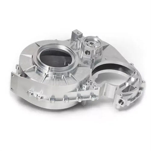
The clamping and alignment of large internal tapered holes in cast iron are key to ensuring taper accuracy, and the appropriate clamping method must be selected based on the workpiece structure. For box-type parts, bottom and side positioning is used, and the parts are fixed to the faceplate with a pressure plate. The flatness of the bottom surface is aligned to ≤0.02mm, and the parallelism of the side surface with the spindle axis is ≤0.01mm/m, ensuring the positional accuracy of the tapered hole axis and the reference surface. For large disc-type parts, a four-jaw single-action chuck is used for clamping, and the outer circle and end face are aligned using a dial indicator. The radial runout of the outer circle is ≤0.02mm, and the axial runout of the end face is ≤0.03mm. After alignment, a pressure plate is used to assist in clamping to prevent loosening during processing. Workpiece deformation must be avoided during clamping. For thin-walled boxes, the clamping force should be evenly distributed, and the force of each pressure plate should be ≤1000N. Copper sheets can be placed between the pressure plate and the workpiece to increase the contact area. Locate the starting and ending positions of the tapered hole, and use the marking method or template to determine the large and small end diameter positions of the tapered hole, with a deviation of ≤0.1mm.
Methods for turning large internal tapered holes in cast iron include toolholder indexing, tailstock offsetting, and profiling. Different methods are suitable for different precision requirements and production batches. The toolholder indexing method is suitable for single-piece and small-batch production. By rotating the toolholder by half the taper angle, manual feed is used for turning. It is simple to operate and easy to adjust, but the feed rate is uneven, and the surface roughness Ra ≥ 3.2μm. It is suitable for applications with low taper accuracy requirements (≤ 0.02mm/100mm). The tailstock offset method is suitable for CNC machining long taper holes. By offsetting the tailstock, the workpiece axis forms a taper angle with the spindle axis, and manual feed is used for turning. The surface quality is good (Ra ≤ 1.6μm) and the taper accuracy can reach 0.01mm/100mm. However, adjustment is complex and suitable for mass production. The profiling method is suitable for high-precision large internal tapered holes (taper error ≤ 0.005mm/100mm). The tool feed trajectory is controlled by a profiling device, achieving automatic feed. The surface roughness Ra ≤ 0.8μm is suitable for large-scale production of box parts.
Cutting parameters for large internal tapered holes in cast iron depend on the tool material and CNC machining stage, with parameters differing significantly between rough turning and finish turning. For rough turning, a YG8 carbide tool should be used at a cutting speed of 60-80 m/min, a feed of 0.2-0.3 mm/r, and a depth of cut of 2-4 mm to quickly remove stock while ensuring a 1-2 mm finish stock on the tapered surface. During rough turning, chips break up and need to be cleaned promptly to prevent accumulation in the tapered hole and scratching the surface. For finish turning, increase the cutting speed to 80-100 m/min, reduce the feed to 0.1-0.15 mm/r, and use a depth of cut of 0.5-1 mm. Use kerosene as a cutting fluid (primarily for lubrication when cutting cast iron) to minimize tool wear and surface roughness. For harder cast iron (such as HT300), reduce the cutting speed by 10%-20% to prevent tool overheating. For castings with pinholes and pores, limit the feed rate to prevent tool chipping.
Quality inspection and error correction for large internal taper holes in cast iron require specialized tools and methods to ensure compliance with design requirements. Taper accuracy is verified using a taper plug gauge or angle ruler. The color-coated plug gauge should ensure contact area ≥ 70%, with evenly distributed contact marks. The angle ruler should measure taper angle error ≤ ±5′. Dimensional accuracy is verified using an inside micrometer or vernier caliper, with tolerances within ±0.03mm for both the large and small end diameters. Surface roughness is measured using a roughness meter, with an Ra value ≤ 3.2μm. After finish turning, surface burrs should be removed and lightly polished in a circular direction with fine emery cloth. Common quality issues and solutions: If the taper error exceeds tolerance, the toolholder indexing method requires readjustment of the angle, while the tailstock offset method requires correction of the offset. If scratches appear on the surface, check the tool edge for sharpness and replace or sharpen it promptly. If the dimension exceeds tolerance, use trial cuts, measuring every 0.1mm infeed, to gradually approach the required dimension. For large inner tapered holes (IT6 grade) with high precision requirements, grinding or honing is required after turning to further improve the precision and surface quality and meet the needs of precise matching.