Structural elements of shaft and sleeve parts
Shafts and sleeves are core components in mechanical equipment that provide support, transmission, and positioning, and are widely used in machine tools, automobiles, construction machinery, and other fields. Shafts are primarily used to transmit torque and support rotating parts (such as gears and pulleys), while sleeves often serve as bearing seats, guide sleeves, or seals, working with shafts to achieve relative motion. While their structures differ, both are characterized by a rotating body and share several common structural elements. The design and CNC machining accuracy of these elements directly impact the assembly performance and operational reliability of the entire machine. Understanding the structural elements of shafts and sleeves is the foundation for their design, CNC machining, and inspection.
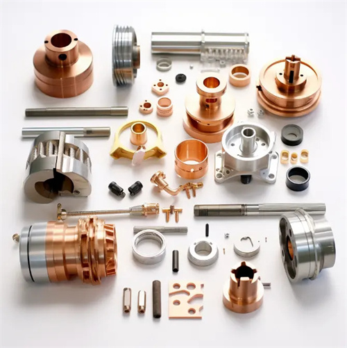
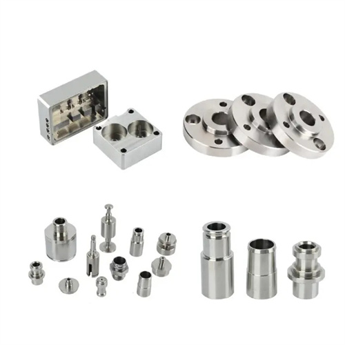
The main structural elements of shaft parts include the journal, shaft head, shaft body, and shoulder, each with distinct functions and structural characteristics. The journal, which mates with the bearing, is divided into support journals (bearing radial loads) and drive journals (transmitting torque). Its diameter accuracy is typically IT6-IT8, with a surface roughness of Ra ≤ 1.6μm. To ensure proper fit with the bearing, the journal’s roundness tolerance is ≤ 0.005mm, and its cylindricity tolerance is ≤ 0.01mm/100mm. The shaft head, which mounts the hub (such as a gear or coupling), is often machined with a keyway, spline, or thread. The keyway’s symmetry tolerance is ≤ 0.02mm, and the depth tolerance is h11. The spline’s centering accuracy can reach IT6 when centered on the minor diameter. The shaft body, connecting the journal and shaft head, is typically cylindrical, with a length determined by structural requirements. Shafts with an aspect ratio greater than 20 are considered slender shafts and require special processing to prevent CNC machining deformation. The shoulder is used for axial positioning. The verticality error between its end face and the axis is ≤0.01mm/m. The height is designed according to the positioning requirements and is generally 3-10mm. If necessary, it can be processed into 45° or rounded transition to avoid stress concentration.
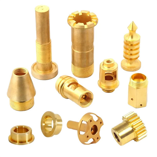
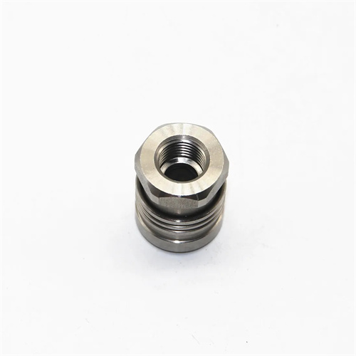
The structural elements of sleeve-type parts are centered around the hole, including the inner bore, outer diameter, end face, stopper, and oil groove. Their precision requirements match those of shaft-type parts. The inner bore is the primary mating surface of sleeve-type parts, and the fit with the shaft is typically a clearance fit (e.g., H7/g6) or a transition fit (e.g., H7/k6). Diameter accuracy is IT7-IT8, with a surface roughness of Ra ≤ 1.6μm. For precision parts such as guide sleeves, the cylindricity error of the inner bore is ≤ 0.005mm/100mm. The outer diameter, used to mate with the housing or frame, is generally less precise than the inner bore, reaching IT8-IT9, with a surface roughness of Ra ≤ 3.2μm. Some sleeve-type parts have threads or undercuts on the outer diameter, with thread accuracy of 6g or 6h. The end face must maintain a high perpendicularity to the inner bore (≤ 0.01mm/m) to ensure axial positioning accuracy. The stopper, used to connect sleeve-type parts, has a diameter tolerance of H8 and a depth tolerance of ±0.1mm. The oil groove is used to store lubricating oil. It is usually annular or spiral in shape, 3-5mm in width, 1-2mm in depth, and has a groove bottom radius of R0.5-1mm to avoid scratching the shaft surface.
Auxiliary structural elements of shaft and sleeve components include chamfers, fillets, undercuts, overruns, and center holes. While these elements don’t directly affect the fit, they significantly impact CNC machining and performance. Chamfers are used to remove sharp edges, protecting operators and assembly surfaces. Chamfers are typically C1-C3 (45° chamfers with a side length of 1-3mm). Shaft end chamfers facilitate sleeve assembly, while hole chamfers prevent scratching of the journal. Fillets are used at transition points such as shoulders and steps. With a radius of R0.5-5mm, selected based on the shaft diameter, they reduce stress concentration and improve part fatigue strength. For example, a R2-R3 shoulder radius on a drive shaft can increase fatigue life by over 30%. Undercuts and overruns are used to remove the tool. They are 2-5mm wide and 0.5-2mm deep and designed according to standards (such as GB/T 3-1997) to ensure the tool does not damage the machined surface. The center hole is the positioning reference for CNC machining shaft parts and is divided into Type A (without cone guard), Type B (with cone guard) and Type C (with thread). The accuracy is in accordance with GB/T 145-2001. The surface roughness of the 60° cone surface is Ra≤1.6μm. For long shafts, center holes must be machined at both ends, and the coaxiality error is ≤0.02mm.
The materials and heat treatment of shaft and sleeve components play a decisive role in the performance of these structural elements and should be selected based on operating conditions. Shaft components are often made of 45 steel (quenched and tempered to 220-280 HBW) and are suitable for medium-speed and medium-load applications. For high-speed, heavy-load shafts, 40Cr (quenched and tempered with a case hardening of 50-55 HRC) or 20CrMnTi (carburized and quenched to 58-62 HRC) are used to improve surface hardness and wear resistance. Sleeve components are commonly made of gray cast iron (HT200, HT300), which offers excellent wear resistance and vibration damping properties and is suitable for components such as bearing seats. Load-bearing sleeve components are made of 45 steel or brass (H62). Brass sleeves can operate without lubrication and are suitable for low-speed and light-load applications. The heat treatment process must be tailored to the structural elements. For example, a surface hardening depth of 1-3mm for shaft necks ensures wear resistance while maintaining core toughness. If the inner bore of sleeve components requires grinding, aging treatment is required to relieve stress and prevent deformation after grinding. By rationally designing structural elements, selecting materials and heat treatment processes, shaft and sleeve parts can meet the comprehensive requirements of strength, precision and life.