Boring a workpiece on a lathe
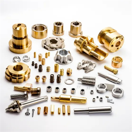
Boring a workpiece on a lathe utilizes the lathe’s spindle rotation and toolholder feed motion to machine the workpiece’s internal hole. This process is suitable for CNC machining various cylindrical and conical internal holes and internal threads, and is particularly well-suited for small-batch production or CNC machining the internal holes of large workpieces. Compared to boring on a drilling machine, lathe boring achieves higher dimensional accuracy (IT7-IT8), form and position accuracy (roundness ≤ 0.01mm, cylindricity ≤ 0.02mm/100mm), and surface quality (Ra ≤ 1.6μm) through the high-speed spindle rotation and precise toolholder feed. It is widely used in CNC machining the internal holes of parts such as housings, sleeves, and flanges. Lathe boring offers great flexibility, allowing adjustments in tool angle and cutting parameters to accommodate internal hole CNC machining in different materials (steel, cast iron, non-ferrous metals, etc.) and with varying precision requirements.
The tool selection for boring workpieces on a lathe depends on the diameter, depth, and precision requirements of the internal hole. Commonly used boring tools include integral boring tools, clamped boring tools, and floating boring tools. Integral boring tools are made of high-speed steel (such as W18Cr4V) and have cutting edges that can be ground to optimal geometry . They are suitable for CNC machining small diameter (≤ 50mm) internal holes with high precision requirements. The tool rake angle is 5°-10°, the clearance angle is 6°-12°, and the lead angle is selected based on the hole depth: 90° for shallow holes and 75°-85° for deep holes. Clamped boring tools use carbide inserts (such as YT15 or YG8) that are fixed to the toolholder with screws. The inserts can be quickly replaced and are suitable for CNC machining medium diameter internal holes (50-200mm). They offer high cutting efficiency and the insert geometry can be adjusted according to the material being machined. The rake angle is 0°-5° for steel and -5°-0° for cast iron. The floating boring tool consists of two symmetrical blades that can float freely in the groove of the tool shank and automatically center itself based on the cutting force. It is suitable for precision boring processes and can effectively improve the roundness and dimensional accuracy of the inner hole. After processing, the dimensional tolerance of the inner hole can reach IT6 level, and the surface roughness Ra≤0.8μm, making it suitable for precision inner hole processing in mass production.
The clamping method for boring workpieces on a lathe must be selected based on the workpiece’s structure and size to ensure stability and precision during CNC machining. For small and medium-sized workpieces (weighing ≤50kg), a three-jaw self-centering chuck can be used. This is suitable for workpieces with pre-machined outer diameters. After clamping, a dial indicator should be used to calibrate the outer diameter’s radial runout to ≤0.02mm and the end face’s axial runout to ≤0.03mm. For large workpieces or those with irregular shapes, a four-jaw single-action chuck or faceplate is required. A four-jaw chuck allows precise alignment of the workpiece by adjusting the position of the four jaws, achieving a radial runout of ≤0.01mm after alignment. The faceplate can be fitted with auxiliary devices such as angle irons and pressure plates, making it suitable for CNC machining workpieces requiring high perpendicularity between the end face and the inner bore (perpendicularity ≤0.01mm/m). For deep hole workpieces with an aspect ratio greater than 5, a one-clamp and one-top clamping method is required. The tailstock center provides auxiliary support to prevent the workpiece from bending and deforming during the boring process. At the same time, a tool rest or guide sleeve is used to ensure the stability of the boring tool to avoid taper or drum-shaped errors in the inner hole.
The CNC machining process for boring workpieces on a lathe is carried out in stages, including rough boring, semi-finishing boring, and finishing boring, gradually improving the accuracy of the inner hole. The purpose of rough boring is to remove most of the allowance, using larger cutting parameters: cutting speed of 50-80m/min, feed rate of 0.2-0.3mm/r, cutting depth of 1-3mm. After rough boring, a semi-finishing allowance of 0.5-1mm is left in the inner hole. Attention should be paid to chip removal at this stage to prevent chips from clogging the inner hole and causing damage to the tool. Semi-finishing boring corrects the shape error after rough boring. Cutting speed of 80-120m/min, feed rate of 0.1-0.2mm/r, cutting depth of 0.3-0.5mm. After semi-finishing boring, a finishing allowance of 0.1-0.3mm is left in the inner hole, while ensuring that the straightness and cylindricity of the inner hole meet the requirements. Fine boring is a key process to ensure the final accuracy. It adopts smaller cutting parameters, cutting speed of 100-150m/min (higher for non-ferrous metals), feed rate of 0.05-0.1mm/r, and cutting depth of 0.1-0.3mm. High-precision boring tools are required for fine boring. If necessary, cutting fluid with good cooling and lubricating properties (such as extreme pressure emulsion and sulfurized oil) should be used to reduce tool wear and inner hole surface roughness.
Common problems and solutions when boring workpieces on a lathe are crucial for ensuring CNC machining quality. If taper errors occur on the inner hole, this is often caused by misalignment between the lathe guideway and the spindle axis or uneven tool wear. Adjust the guideway clearance or replace the tool. If the inner hole roundness is out of tolerance, this may be due to loose workpiece clamping, excessive spindle bearing clearance, or insufficient tool rigidity. Re-clamp the workpiece, adjust the spindle bearings, or select a more rigid toolholder (the toolholder diameter should be no less than 1/3 the hole diameter). If chatter marks appear on the inner hole surface, reduce the cutting speed, increase the feed rate, or adjust the spindle speed to avoid resonant frequencies. If the hole diameter is out of tolerance, regularly calibrate the gauge, adjust the boring tool size, or use trial cuts to control the size. For deep hole boring (hole depth L to diameter D ratio L/D > 5), pay attention to toolholder cooling and chip removal. Internally coolant toolholders can be used to spray cutting fluid directly into the cutting area. Spiral chip flutes can also be used to ensure smooth chip removal and prevent chip scratches on the machined surface. By rationally selecting cutting tools, optimizing clamping methods, and controlling cutting parameters, high-precision internal holes can be stably bored on a lathe to meet the use requirements of various mechanical parts.