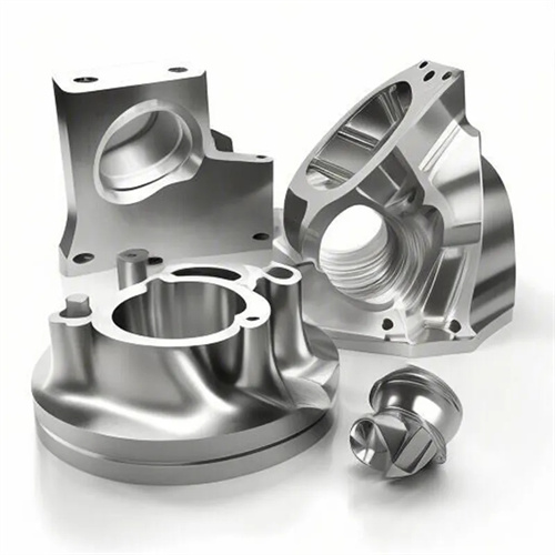
CNC Machining of cast aluminum alloy bracket
Cast aluminum alloy brackets are important structural components in aerospace, automotive, and electronic equipment applications. They feature light weight (density 2.6-2.8g/cm³), moderate strength (tensile strength 150-300MPa), and corrosion resistance. Their structures typically include flat surfaces, holes, steps, and threads, used to support, position, or connect other parts. Cast aluminum alloys (such as ZL101 and ZL104) offer excellent casting properties, but surface defects such as pores, pinholes, and shrinkage may exist. During turning, appropriate process measures tailored to the material’s properties (good plasticity, ease of tool sticking, and rapid heat dissipation) are required to ensure CNC machining accuracy (IT7-IT9 grades) and surface quality (Ra ≤ 1.6μm).
When selecting turning tools for cast aluminum alloy brackets, it’s crucial to address tool sticking and surface roughness. Common tool materials include high-speed steel, cemented carbide, and diamond. High-speed steel tools (such as W18Cr4V) are suitable for low-speed finish turning. They feature a sharp cutting edge and produce excellent surface quality. A rake angle of 15°-20°, a clearance angle of 10°-12°, and a cutting edge inclination angle of 5°-10° reduce friction between the chip and the rake face, preventing tool sticking. Carbide tools are suitable for high-speed cutting. When CNC machining aluminum alloys with high silicon content, such as ZL101, YG-type carbides (such as YG6X and YG8) are recommended for their excellent wear resistance and resistance to aluminum sticking. When CNC machining pure aluminum or low-silicon aluminum alloys, YT-type carbides (such as YT15) are recommended. A rake angle of 10°-15° and a clearance angle of 8°-10° are recommended. The cutting edge should be ground with a negative chamfer of 0.1-0.2mm to enhance edge strength. Diamond tools (natural diamond or PCD) are suitable for high-precision and high-finish processing, and can achieve mirror turning (Ra≤0.025μm). The tool rake angle is 0°-5°, and the back angle is 5°-8°. It is suitable for applications requiring surface roughness Ra≤0.8μm.
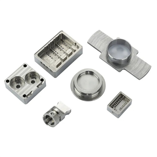
Bracket surface processing.
When clamping cast aluminum alloy brackets, deformation and surface damage must be prevented. Select an appropriate clamping method based on the bracket’s structure and size. For small brackets (weighing ≤ 5kg), a three-jaw self-centering chuck is used. The jaws should be softened (hardness ≤ 200 HBW) or covered with rubber sleeves to prevent damage to the workpiece surface. The radial runout of the outer diameter after clamping should be ≤ 0.03mm. For medium-sized brackets (5-20kg), a four-jaw chuck or faceplate is used for clamping. Positioning is achieved using a flat surface or a process boss, and clamping is achieved using a pressure plate. An aluminum plate (1-2mm thick) is placed between the pressure plate and the workpiece. The clamping force should be controlled between 500-800N to prevent plastic deformation in thin-walled areas (wall thickness ≤ 3mm). For large brackets (weighing > 20kg), a dedicated fixture is used. The positioning elements in the fixture are made of nylon or brass to prevent scratching of the workpiece. Positioning accuracy is ≤ 0.02mm. The clamping mechanism is pneumatically or hydraulically driven to ensure uniform clamping and reduce operator error. Before clamping, the burrs and oil stains on the workpiece positioning surface must be cleaned to ensure accurate positioning.
The turning process for cast aluminum alloy brackets requires a phased approach, balancing efficiency and precision. The general process route is: rough turning → aging → semi-finishing → finishing. During rough turning, the riser and most of the casting’s stock are removed, leaving a 1-2mm stock on flat surfaces and a 0.5-1mm stock on holes. High-speed cutting is employed (carbide tools, cutting speeds of 300-500m/min), with a feed rate of 0.2-0.3mm/r and a depth of cut of 2-4mm. Minor surface imperfections can be tolerated during this stage; the focus is on rapidly removing stock. After rough turning, aging treatment (artificial aging at 120-150°C for 2-4 hours) is performed to eliminate CNC machining stresses and prevent subsequent deformation. Especially for brackets with complex structures, aging can reduce residual stress by 40%-60%. Semi-finishing turning corrects rough turning errors, allowing a 0.3-0.5mm allowance for flat surfaces and a 0.1-0.3mm allowance for holes. Cutting speeds are 200-300m/min, feed rates are 0.1-0.2mm/r, and surface roughness Ra ≤ 3.2μm. Finishing turning ensures final accuracy, CNC machining flat surfaces and holes to design dimensions. Cutting speeds are 100-200m/min (high-speed steel tools) or 400-600m/min (diamond tools), feed rates are 0.05-0.1mm/r, and surface roughness Ra ≤ 1.6μm. For surfaces requiring sealing, Ra ≤ 0.8μm is required.
Targeted turning measures are required for key areas of cast aluminum alloy brackets to ensure they meet operational requirements. For flat turning, a carbide facing tool should be used with a lead angle of 90°-95° to prevent excessive cutting forces and workpiece deformation. For finish turning, a wide-blade tool (10-20mm blade width) can be used, achieving high-speed finishing at a feed rate of 0.05-0.1mm/r, with a flatness error of ≤0.02mm/100mm. Hole CNC machining should be performed first with a high-speed steel drill, followed by boring with a carbide boring tool. For small holes with a diameter of ≤10mm, a solid carbide drill and boring tool should be used to minimize tool vibration. For large holes with a diameter greater than 50mm, an indexable boring tool should be used to ensure an IT7 aperture tolerance and a cylindricity error of ≤0.01mm/100mm. Threads are machined using high-speed steel taps or thread turning tools. Kerosene or specialized aluminum alloy cutting fluid is added during tapping to prevent sticking and thread rot. Thread accuracy can reach 6H or 6g. When turning the step surface, the perpendicularity between the step end face and the axis must be maintained at ≤0.01mm/m. A two-pass tooling approach can be used: rough turning the step’s outer diameter and end face, followed by finish turning the end face, to eliminate deformation caused by turning the outer diameter.
Strict quality inspection and defect handling of cast aluminum alloy brackets are required to ensure product quality. Dimensional accuracy is verified using a vernier caliper, micrometer, or internal diameter gauge, with a tolerance of ±0.05mm for flat dimensions and IT8 for hole diameters. Form and position accuracy is verified using a dial indicator, square, or coordinate measuring instrument, with flatness ≤0.03mm/100mm and verticality ≤0.02mm/m. Surface quality is inspected visually and using a roughness tester. Surface defects such as cracks and shrinkage must be avoided, with a roughness Ra ≤1.6μm. Porosity, sand holes, and other defects discovered during turning, if ≤0.5mm in diameter and small in number, can be repaired with aluminum putty and reprocessed after curing. Severe defects require scrapping. Common CNC machining problems and solutions: If surface buildup occurs, increase the cutting speed, increase the rake angle, replace the diamond tool, and enhance cutting fluid cooling. If the workpiece deforms, optimize the clamping method, using multiple clamping points or adding auxiliary supports. If the dimensions are out of tolerance, regularly calibrate the measuring tools and use trial cuts to control the final dimensions. By selecting the right tool, clamping method, and process parameters, high-quality cast aluminum alloy brackets can be consistently produced to meet the requirements of various equipment.