Brass Copper CNC Machining: Machine Setup and Precision Foundations
Achieving high precision in brass and copper CNC machining begins with establishing robust machine setups that account for each material’s unique characteristics. We invest in high-precision CNC machines with positioning accuracy of ±0.0005 mm and repeatability of ±0.0002 mm, essential for tight-tolerance brass and copper components. For brass, which maintains dimensional stability during machining, we focus on calibrating spindle runout to below 0.001 mm to ensure consistent cutting. For copper, with its higher thermal sensitivity, we implement thermal compensation systems that adjust for temperature fluctuations in real time, as even small heat changes can affect dimensional accuracy. We use precision toolholders with minimal runout (<0.002 mm) for both materials, but particularly for copper to prevent surface finish defects. Regular machine calibration, performed weekly, verifies axis alignment and backlash compensation, ensuring our setups maintain precision across production runs. By establishing these foundational practices, we create the conditions necessary for high-precision machining of both brass and copper components.
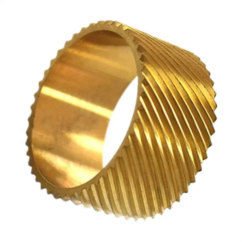
Brass Copper CNC Machining: Tool Selection and Geometry Optimization
Selecting the right tools and optimizing their geometry is critical for achieving high precision in brass and copper CNC machining. For brass, we use carbide tools with positive rake angles (8-12 degrees) and sharp cutting edges that minimize burr formation while maintaining tight tolerances. Uncoated carbide inserts work exceptionally well for brass, providing long tool life and consistent performance. For copper, we prioritize sharp tools with polished flutes to reduce material smearing and improve chip evacuation—polycrystalline diamond (PCD) tools are our choice for critical features, as they maintain edge sharpness longer than carbide. We adjust tool geometry based on material: brass benefits from higher helix angles (30-35 degrees) for efficient chip removal, while copper requires slightly lower helix angles (25-30 degrees) to reduce cutting pressure. Tool diameter selection is also material-specific, with larger diameter tools used for brass to leverage its rigidity and smaller, more rigid tools for copper to minimize deflection.
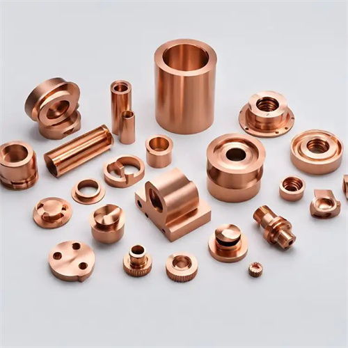
Brass Copper CNC Machining: Fixturing Solutions for Dimensional Stability
Effective fixturing is essential for maintaining precision in brass and copper CNC machining, as both materials respond differently to clamping forces. For brass, which is more rigid, we use high-precision vises with hardened jaws that provide secure clamping without deformation, allowing for aggressive cutting parameters while maintaining tolerance. We implement 3-2-1 locating principles to ensure consistent part positioning, achieving repeatability within ±0.001 mm across batches. For copper, with its lower hardness and higher ductility, we use soft-jawed fixtures lined with copper or brass inserts to distribute clamping force evenly, preventing workpiece distortion. Vacuum chucks are employed for thin-walled copper components, applying uniform holding pressure without mechanical stress points. We also use modular fixturing systems that allow quick changeovers between brass and copper parts while maintaining positioning accuracy, ensuring our setups support the precision requirements of both materials.
Brass Copper CNC Machining: Cutting Parameters for Precision Control
Optimizing cutting parameters specifically for brass and copper is key to achieving high precision in CNC machining, as each material responds differently to cutting forces. For brass, we use higher cutting speeds (250-300 m/min) with moderate feed rates (0.1-0.15 mm/tooth) to leverage its excellent machinability while maintaining dimensional control. This combination produces clean cuts with minimal burr formation, reducing the need for secondary finishing. For copper, we employ lower speeds (150-200 m/min) with reduced feed rates (0.08-0.12 mm/tooth) to manage its tendency to work-harden and maintain surface integrity. We adjust depth of cut based on material: brass handles deeper cuts (0.5-1 mm) without dimensional changes, while copper requires lighter passes (0.2-0.5 mm) to prevent tool deflection and workpiece distortion. Coolant application is also material-specific—high-pressure coolant (70-100 bar) for brass to flush chips, and directed coolant for copper to control heat buildup at the cutting interface.

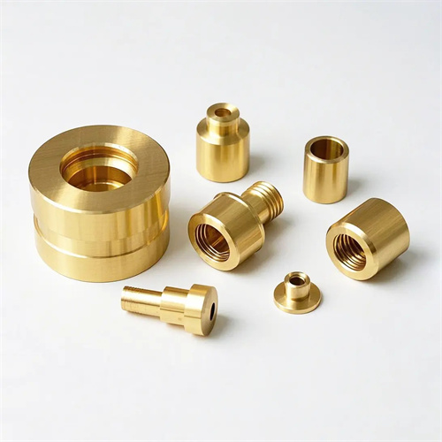
Brass Copper CNC Machining: In-Process Measurement and Quality Control
Implementing rigorous in-process measurement ensures high precision in brass and copper CNC machining by catching deviations before they affect final part quality. We integrate probing systems into our CNC machines that measure critical features during machining, with accuracy down to 0.0005 mm. For brass components, we perform measurements after roughing and finishing operations, verifying dimensions against CAD models to ensure compliance with tolerances as tight as ±0.002 mm. For copper, which is more prone to post-machining dimensional changes, we add intermediate measurements during the machining process to account for potential thermal expansion. We use statistical process control (SPC) for both materials, analyzing measurement data to identify trends and adjust parameters proactively. Special attention is paid to critical features: thread pitch diameter for brass fasteners and flatness for copper heat sinks, ensuring these key characteristics meet specification before parts leave the machine.
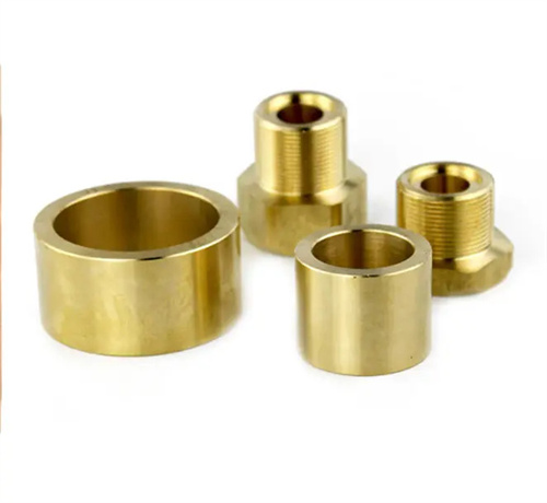
Brass Copper CNC Machining: Surface Finish and Tolerance Achievement
Achieving precise surface finishes and tight tolerances requires material-specific strategies in brass and copper CNC machining. For brass, we focus on minimizing burr formation through sharp tools and optimized feed rates, achieving surface finishes as low as Ra 0.4 μm for decorative or sealing surfaces. Tolerances of ±0.001 mm are consistently achieved for brass components using rigid setups and stable cutting parameters. For copper, surface finish excellence requires preventing smearing and tearing—we use light finishing passes with PCD tools, achieving Ra values below 0.8 μm even on complex geometries. To maintain copper’s dimensional accuracy, we allow parts to stabilize at room temperature after machining before final inspection, compensating for thermal contraction in our measurements. We also implement specialized deburring processes for copper, as its softness makes burr removal more challenging. By tailoring our approach to each material’s properties, we consistently achieve the high precision required for critical brass and copper components.